- Mobile:+86 17561919576
- WhatsApp:+86 17561919576
- Email:business@cexcasting.com
CNC Machining
CEX SERVICES
REQUEST A FREE QUOTE
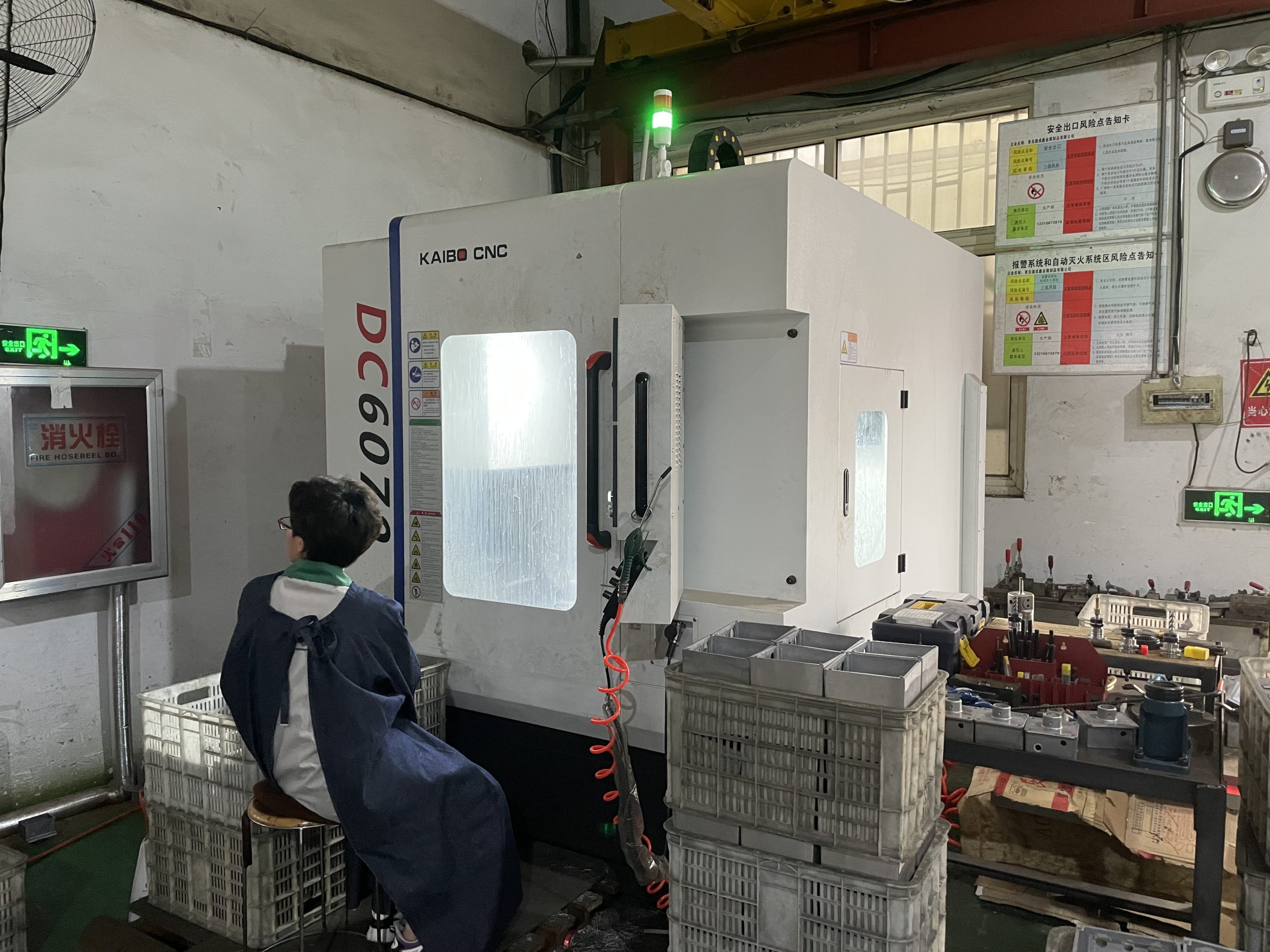
General CNC machining usually refers to computer digital control precision machining, CNC machining lathes, CNC machining milling machines, CNC machining boring and milling machines, etc.
Determination of CNC machining route
The CNC lathe feed processing route refers to the path that the turning tool moves from the tool setting point (or the fixed origin of the machine tool) until it returns to this point and ends the processing program, including the cutting processing path and the non-cutting such as cutting in and out of the tool. Empty travel path.
The feed route of finishing is basically carried out sequentially along its part contour, therefore, the focus of the work to determine the feed route is to determine the feed route of rough machining and idle travel.
In CNC lathe processing, the determination of the processing route generally follows the following principles.
①It should be able to ensure the accuracy and surface roughness of the workpiece to be processed.
②Make the processing route the shortest, reduce the idle travel time, and improve the processing efficiency.
③ Try to simplify the workload of numerical calculation and simplify the processing program.
④For some repeated programs, subroutines should be used.
cNC Machining advantages And disadvantages
CNC machining has the following advantages:
① The number of tooling is greatly reduced, and complex tooling is not required to process parts with complex shapes. If you want to change the shape and size of the part, you only need to modify the part processing program, which is suitable for new product development and modification.
②Stable processing quality, high processing precision and high repeatability, which can meet the processing requirements of aircraft.
③ The production efficiency is high in the case of multi-variety and small batch production, which can reduce the time for production preparation, machine tool adjustment and process inspection, and the cutting time is reduced due to the use of the optimal cutting amount.
④ It can process complex profiles that are difficult to process by conventional methods, and even process some unobservable processing parts.
The disadvantage of CNC machining is that the machine tool is expensive and requires a high level of maintenance personnel.
what is cNC Machining?
CNC machining refers to the machining performed with CNC machining tools. CNC index-controlled machine tools are programmed and controlled by CNC machining language, usually G code. The CNC machining G code language tells the CNC machine tool which Cartesian position coordinates the machining tool adopts, and controls the tool feed rate and spindle speed, as well as tool changer, coolant and other functions. CNC machining has great advantages over manual machining. For example, the parts produced by CNC machining are very accurate and repeatable; CNC machining can produce parts with complex shapes that cannot be completed by manual machining. CNC machining technology has been widely promoted, and most machining workshops have CNC machining capabilities. The most common CNC machining methods in typical machining workshops are CNC milling, CNC turning and CNC EDM wire cutting (Wire EDM).
The tools for CNC milling are called CNC milling machines or CNC machining centers. A lathe that performs CNC turning is called a CNC turning center. CNC machining G codes can be programmed manually, but usually machine shops use CAM (Computer Aided Manufacturing) software to automatically read CAD (Computer Aided Design) files and generate G code programs to control CNC machine tools